Parallel Circuits
Last time we looked at what happens to voltage and current when we have resistors in series, which means one after the other in the same loop or path. If instead we have resistors forming separate paths or loops, we say they are in parallel.
Here is an example of a parallel circuit:

Notice that the 5V line coming out of the power supply splits into two branches, which then join back up at GND. Parallel branches give the electrons more than one possible routes to take, but regardless of their choice, they still have to “lose” the 5V they gained from the power supply before returning to the negative terminal. So each branch is functionally the same as our simple LED circuit from Lesson 2, you can think of the above circuit like this, but with the two circuits sharing the power supply:

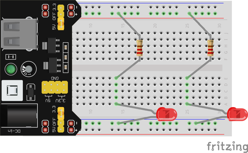
Go ahead and build the parallel circuit, PLEASE USE IDENTICAL RED (or yellow) LEDs FOR THIS EXERCISE. One way to construct it on the breadboard is like this (though as always, there are many ways to accomplish this):
We’re going to take a look at what happens to current when we give electrons multiple paths like this. Let’s start by using Ohm’s Law to predict the current through each branch, and then measure to verify.

The current I1 is the current through the first branch. Remembering what we know about components in series, this is the same this as the current through just the resistor R1. So if we know VR1 (the voltage drop across R1), we can us Ohm’s Law to calculate IR1, which is the same this as I1.
Measure and record VR1. You should get around 3V.
Using your measured VR1, calculate and record I1 using Ohm’s Law:
I = V / R I1 = VR1 / R1
I1 = ~3V / 220Ω
I1 = ~0.0136A
I1 = ~14mA
Just as before, our 220Ω resistor limits the current to the LED to about 14mA.
Verify this result by measuring and recording I1 in the same way we’ve done in previous lessons. When you break the connection between R1 and LED1 to do this, causing LED1 to turn off until you reconnect it to R1 with the detour through the multimeter, you should notice that LED2 stays lit the whole time. This is because we haven’t interrupted the path there. Hopefully your measurement is close enough to your calculated prediction.
Repeat the above process for the 2nd branch, measure and record VR2 and then use Ohm’s Law to calculate and record I2.
NOTE: Older versions of the workbook contain some typos, including the labels in the 2nd row of boxes for this exercise. They should read: “VR2”, “I2 (calc.)”, and “I2 (meas.)”
Once you measured VR2 and found it basically the same as VR1 (I hope, otherwise maybe go back a few lessons), you could probably guess what I2 was going to be: again around 14mA. Remember, the electrons have to “use up” the 5V no matter which path they take, so if the voltage drop is going to be the same, and the components they are passing through are identical, there shouldn’t be any difference in how fast they flow.
But what does this mean for the current before and after the fork in the road? In other words, but much current in total is flowing out of and back into the power supply, labelled Itot in our schematic?
Kirchoff’s Current Law
To measure Itot, we’ll need to get a bit fancy. Remember that to measure current we need to break the circuit, and then reconnect it with a detour through the multimeter. This was easy in the branches, the connection we broke involve two long exposed conductors to touch the probes to. Since the probes don’t fit in the breadboard holes, we can’t take the exact same approach.
Here’s one way to measure Itot, but as usual there are many other creative ways you might come up with. Just make sure that this time, when you break the circuit, both LEDs turn off, since we are dealing with the source of both branches (imaging damming a river before a split into two streams).
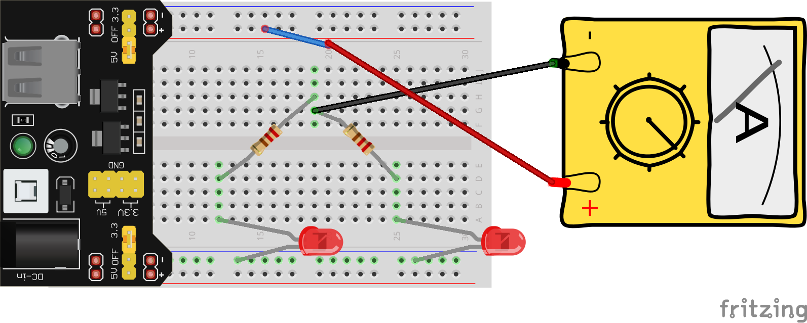
In this image, the small blue wire is exactly that, just a small piece of wire with one end stuck in the 5V rail, and the other end loose and exposed. Your kit comes with a set of preformed breadboarding wire in various lengths. We’ll use these a lot more later on to make connections between breadboard rows when things get more complicated, but this is another handy application.
I’ve also moved the first leg of both resistors to a random row, they need to be in the same row for this to work.
Now when I hold the black probe to the loose end of the little blue wire, and the red probe to one of the resistors’ legs (doesn’t matter which one, if they’re in the same row they are effectively just the same piece of wire), both LEDs should turn on and you can read the current on the screen (assuming you’re in 200mA mode). Record your measurement for Itot.
You should find that the total current that this circuit pulls from the power supply is something around 28mA. Compare this to the current you measured in each branch, what relationship do you notice?
It shouldn’t be hard to see that the total current is simply the sum of the current in each branch. This phenomenom is known as Kirchoff’s Current Law (busy guy) which states:
The sum of all currents flowing into a node equals the sum of all currents flowing out of the node
Node here is just a fancy word for junction, split, or fork in the road. It follows then from Kirchoff’s Current Law that the current flowing back into the power supply, after the two branches have joined up again, should also be about 28mA. You can test that for yourself if you like.
The Road Less Travelled
Just like last time, our first example involved identical components, so once again let’s see what happens when we make a small change to our circuit:

Again we are using the 1kΩ resistor, which has the BROWN-BLACK-BLACK-BROWN color code.
If you have very keen eyes, you might notice a slight difference in the brightness of the two LEDs. As we discussed in Lesson 3, bigger resistors mean less current, which means dimmer LED.
Perform all of the same measurements and calculations as we did earlier and record your findings. In addition, see if you can predict Itot in this circuit once you know the current in each branch using Kirchoff’s Current Law.
Things to notice here:
- I2 should be around 4mA. This should make sense, there’s a bigger resistor which means less current.
- I1, meanwhile, stayed the same (14mA). Changing the other branch doesn’t affect this branch. Remember, all that matters for current is a) how much energy the electrons have to lose (V) and b) how difficult the path is (R). Changing the resistor in the other branch doesn’t change the fact that electrons going through the first branch still have to lose 5V while going through the same resistor and LED combo.
- Once again the total current (Itot) should be I1 + I2. This time this is something close to 18mA (14mA + 4mA).