We’ve made it to the end of the components for this first unit, the rest will be covered in the second module when we explore Digital Logic Systems, but to get there we need to understand one of the most important electrical innovations of the modern age: the transistor.
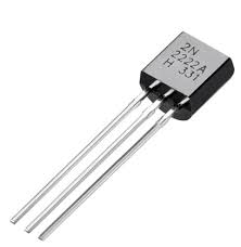
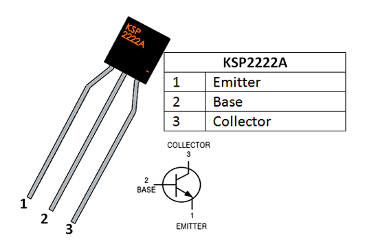
Pictured here is a 2222A Transistor, one of the most common transistors for our scale of electronics and the kind that is in your kit. Specifically, the 2222A is an NPN BJT transistor, but don’t worry about what those mean for this course. It might not look like much, but transistors are the fundamental building blocks of all computing: from the simple logic systems we will build in the next unit with just a few transistors to the billions of transistors that make up a modern CPU.
My AMD 2200G processor is made of just under 5 billion (5,000,000,000) transistors
What’s the Big Deal?
Transistors are actually pretty simple to understand, which is why it’s so amazing to consider the scale and complexity of the computer systems build out of them.
A transistor is just a switch.
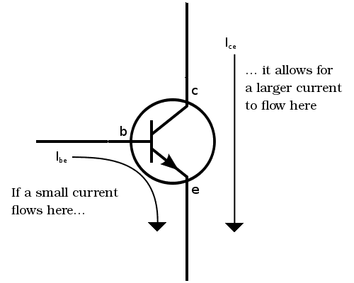
Just like the slide switches and tac-switches in the previous lesson, transistors allow or block current depending on some input. In our physical switches, that input was mechanical: a human hand physically pressing and releasing the button for example. In transistors the input is electrical. BJTs (bipolar junction transistors) have 3 pins: Emitter (e), Base (b), and Collector (c). Here you can see the pinout of the 2222A, as well as the schematic symbol for an NPN transistor.
Think of the collector and emitter like either side of a switch: current can only flow from one to the other if a certain condition is met. An NPN transistor, like our 2222A, is turned “on” if there is a small amount of voltage between the emitter and the base (Veb) which causes a small amount of current to flow into the base.
To find out what voltage is needed between the emitter and base to activate our 2222A transistors, let’s build this circuit, taking care to reference the pinout above to make sure your transistor isn’t backwards:

**Older versions of the workbook may have a slightly different schematic for this lesson, with the 220Ω resistor and the LED after the transistor. Either circuit will work to illustrate the concepts, but this one might be slightly more clear.
What we have here is our standard LED setup with a 220Ω resistor, but rather than going straight to 0v, the LED instead connects to the collector of the transistor, which then has its emitter connected to 0V. From what we discussed above, the LED will only turn on if the transistor is activated.
The base of the transistor is connected to pin 2 of a potentiometer, with pins 1 and 3 of the pot connected to 5V and 0V. Used in this way, the potentiometer lets us set pin 2 to any voltage between 0V and 5V, thus controlling the voltage between the emitter and the base of the transistor. The 10kΩ resisitor (BROWN-BLACK-ORANGE) simply limits the flow of current into the base. Transistors are quite sensitive, too much current in the base will cause them to break.
Double check your connections first, then power on your circuit and test it out. You should find that the LED goes from off to on within a small range of positions on the potentiometer, and while you can keep turning the knob quite a bit more, the LED doesn’t continue getting any brighter.
With the LED off, measure Veb. Then turn the knob until the LED just starts to turn on and measure Veb again. Turn the knob again until the LED reaches its full brightness and measure again. Finally, turn the knob all the way up, even though the LED won’t be getting any brighter, and measure once more.
You should have found that once you pass the point where the LED starts turning on, Veb stays fixed at around 0.7V. This is very similar to the behaviour we’ve seen in LEDs and again here we call it the forward voltage of the transistor. This is the amount of voltage needed at the base to activate the transistor and let current from the collector to the emitter.
So What?
We’ll see a simple application in the project coming up, but for now you’ll have to trust me that transistors are hugely important in the world of digital systems. We’ll see more complex uses in the next unit, NET 1010: Digital Logic Systems, but for now just remember, it’s just a switch.